Prototype battery charger circuit V SIMULATION AND EXPERIMENTAL Circuit Diagram A battery charger circuit uses temperature and voltage sensing circuits along with a microprocessor controller. It adjusts the charging current and voltage based on the battery's state of charge. The circuit increases output voltage to compensate for wire impedance, ensuring safe and efficient charging until the battery reaches full capacity. Design considerations for a battery charger In this video, you will learn the basics of the Battery Charger Circuit Design. The instructor explains the basics of the circuit design. He also explains th

Learn how to build a simple and efficient battery charger circuit with LM317 and relay control. Perfect for charging 4-cell AA batteries with automatic shut-off Learn how to build a battery charger circuit with a detailed schematic and step-by-step instructions. Get your batteries charged efficiently and safely.
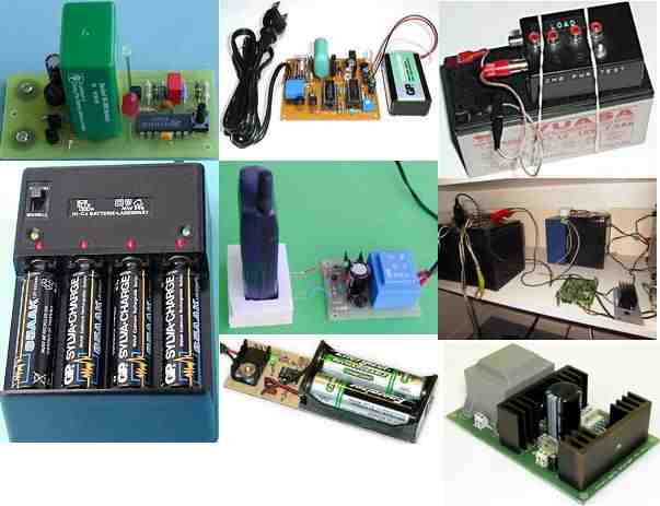
Battery Charger Circuit Design (Part - 1) Circuit Diagram
Prevent mistakes by downloading my DESIGN REVIEW CHECKLISTS for the schematic circuit, PCB layout, and enclosure 3D model design: https://predictabledesigns.

Learn how to build battery chargers for sealed lead acid, NiCd, NiMH, and LiPo batteries. The following section have explained the designing of a customized current control circuit for a specific, selected battery charger unit. Adding a Constant Current Just like the "constant voltage" parameter, the recommended charging current for a particular battery should not be increased or fluctuated by much.
Design considerations for battery charges to achieve the best user ... Circuit Diagram
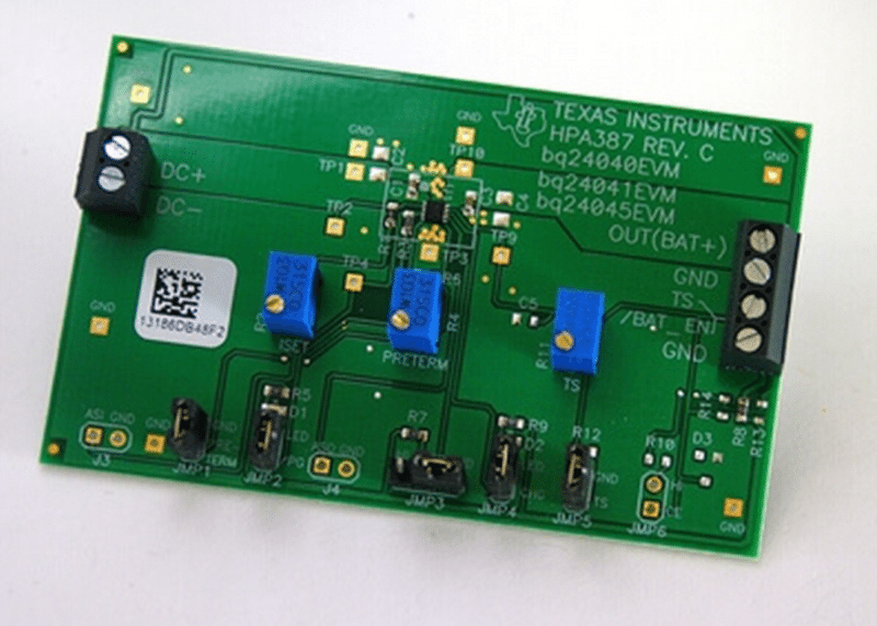
What is DPPM? DPPM monitors the input current, input voltage and output currents of a power-path device and automatically gives priority to the system when the adapter cannot support system and charging loads. The figure shows a DPPM circuit in a linear charger. The same principle applies for switching chargers.
